Podcasting since 2005! Listen to Latest SolderSmoke

Showing posts with label Russia. Show all posts

Sunday, April 28, 2024

A Soviet Tube in Cuba: The "Little Spider"


I hope readers have picked up on the discussion of the Islander DSB rig out of Cuba. We had a bit of a breakthrough on this recently. I've been writing about it on the blog: 

https://soldersmoke.blogspot.com/2024/04/re-building-islander-dsbcw-rig-in-cuba.html 

One thing I think is especially interesting:  The Cubans were using parts taken out of old Soviet TV sets.  One of the tubes used in the VFO section of the Islander was known among the Cuban hams as "the little spider." 

Arnie Coro CO2KK explains why: 

"VFO is made with ONE of the 6 "little spider" 5 pentodes... By the way, I am sure you will like to know why the tube is locally known like that... the ZHE letter of the Cyrillic alphabet is something difficult to pronounce to a Cuban - or any other non slavic for the matter - and it resembles like a little spider on the tube's carton and... that's why it is not a 6 "ZHE" 5 but a 6 "little spider" five!!!"

Thursday, November 30, 2023

AA9IL's Sputnik Tube, Altoids Tin Transmitter

November 24, 2023
Hello Bill
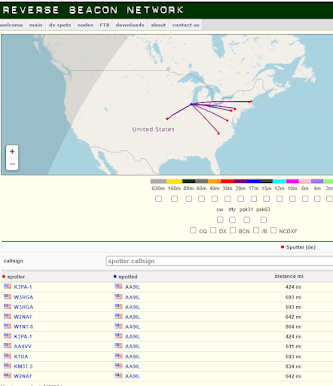
I have just built an tested a 20 meter “Sputnik” transmitter. It uses two Soviet era “rod” tubes and is fixed tuned to 14.060 MHz.  I was able to compress the design to fit in an Altoids tin. The plate tuning capacitor was replaced with a fixed capacitor value closest to the variable for peak power out. Plate voltage is 90 volts and I key both the oscillator and PA via the B+ line. Power output is around 200mW and my first test transmission from the Chicago area was picked up 864 miles away on the east coast via the Reverse Beacon Network. It was definitely Joy of Oscillation and Joy of Transmission!

73, Mike
AA9IL
EN52
----------------

Mike's rig has been heard by many Reverse Beacon Network stations: 


------------------
November 29, 2023
Bill: 
I started a QSO with AC2C in Ellicott, MD who responded to my CQ but the band dropped (20m)
But that’s a good start and I’ll keep at it!  So, yay!
73 Mike
-------------------

Here are some earlier blog post on rigs using Soviet rod tubes: 

Saturday, November 25, 2023

Some Short-Wave Listener QSL Cards

Click for a better view

I haven't received many, but I always like QSL cards from shortwave listeners.  Someone out there is listening!  


The top one is from recent contact. It arrived from Hungary via the W2 QSL bureau.  Here is Tamas HA00001: 


The middle one is from my youth.  in 1975 Nick in Moscow USSR heard my contact with OD5IO.   I didn't remember the contact with Lebanon.  It turns out that the operator was K4NYY (who is now a silent key.  See https://www.qrz.com/db/K4NYY/?mlab=). 


The bottom one pre-dates me by more than twenty years.   It comes from Berlin in 1936. W5AIR was heard working EI7F on 20 meter CW.   Does anyone have any info on this SWL? 

Over on The SWLing Post blog,  readers posted this info: 

Sunday, April 9, 2023

Arnie Coro CO2KK (SK) Provides More Info on the Islander DSB rig

Peter Parker VK3YE found this message from Arnie CO2KK in the Wayback Machine.  We continue to look for more information on the Jaguey solid state DSB rig. 

Arnie wrote: 

Several years ago an amateur in central Cuba was approached by some of his young friends to help them build their first rig. CO7PR, Pedro, a telecommunications technician for the phone company, had a vast experience both with vacuum tubes and solid state circuits, plus that special gift of designing and building with whatever is available. After a few days, Pedro came out with the "Islander" prototype, a low parts count, easy to build single band transceiver!

Here is the circuit description of that little radio that has provided many cuban young and old, newcomers to our hobby, with their first rig... and the challenge to improve it.


RECEIVER:

It is a direct conversion, YES, a DC receiver made with vacuum tubes. The very thought of having those tube filaments fed from the AC power supply and at the same time having 80 or 90 dB of amplification made me shudder when I first talked to Pedro on the very popular here 40 meter band! You are LOCO Pedro, I told my good friend... CRAZY, those poor kids are going to hear 50 percent 120 hZ hum when they tune across the 7 megahertz band.

Yes Arnie, you are right, it has a little background hum, but by using a small loudspeaker and small coupling capacitors... it's tolerable! The receiver shares, in its original version, the same antenna input as the transmitter output stage, a PI network, but we soon learned to add a separate LC tuned circuit first and latter a bandpass double tuned input filter...PLUS a signal attenuator... a very primitive but effective attenuator... just a 10 k potentiometer!

For an RF amplifier stage the Islander uses a russian pentode, which is the equivalent of the popular TV IF amplifiers of the 50's... looks like a 6CB6, for those of you that fixed TV sets 40 years ago or so.

The 6 "little spider" five, as everyone knows that tube here,has a lot of gain, and it can be kept rather stable by a judicious choice of screen and cathode resistor values.. Noisy pentagrid converter follows!

The 6A2P... a russian 6BE6, was the first tube type used in the Islanders, later some people tried the ECH81 triode-hexode and found it works better.

The circuit of the 6A2P-6BE6 is quite straighforward... a... you guessed right... PRODUCT DETECTOR... fed from the vacuum tube VFO... and providing its audio output to the two stage audio amplifier.

Audio amplifier is made with a triode-pentode tube of which plenty are locally available from defunct TV's... the ECL82 and the 6F4P and 6F5P of east european and russian manufacture respectively provide a lot of gain.

So... that's your receiver.. quite straightforward, works on 160, 80 and 40 meters by just changing the input filter and the VFO injection, it does NOT provide very good selectivity at all, but during the daytime, when the 40 meter band is used for local and regional contacts, it puts those new hams ON THE AIR!


VFO... the big problem amigos!

CO7PR worked very hard to try to make a stable vacuum tube VFO... and he almost made it..

YES, ISLANDERS drift, some not too much, others are not so good, depending on who built the rig, and how close they followed Pedro's advice at first, and Arnie's CO2KK later (as yours truly became quite involved in the project, as soon as I found that it was THE way of getting all those guys ON THE AIR!)

VFO is made with ONE of the 6 "little spider" 5 pentodes... By the way, I am sure you will like to know why the tube is locally known like that... the ZHE letter of the Cyrillic alphabet is something difficult to pronounce to a cuban - or any other non slavic for the matter - and it resembles like a little spider on the tube's carton and... that's why it is not a 6 "ZHE" 5 but a 6 "little spider" five!!!

The VFO cleverly works at one half the operating frequency... and then it DOUBLES frequency at the plate circuit... output is via a link to the pentagrid or hexode mixer depending on which type you use.

BUT... the VFO also has a second output to the transmitting chain.. Well that's the receiver... OH YES... the VFO is fed from a VR tube, a gaseous discharge voltage regulator similar to a VR-150 or VR-105... CO7PR advises to use the VR105, but when building the Islander, special in the countryside, that's a very hard part to find, as old TV sets don't use VR tubes! So people use whichever VR they can find. ZENERS? They are only available locally for 6 to 24 volts, so they can't be used with this rig.


ISLANDER DSB AND CW transmitter circuit:

From the VFO plate circuit, you pick up 7 mHz energy (usually you must wait at least half an hour for that said 7 mHz energy to be stable enough in frequency) and feed two diodes (ex-video detectors from russian TV type D20) acting as what I like to call BALANCED AND UNBALANCED modulator!

When used for DSB, it is certainly a DSB generator... but when you want to work CW, it must be UNBALANCED.something easy to achieve with just a resistor from the +12 volts line and a switch!

The balanced modulator receives its audio from a carbon microphone capsule salvaged from an old telephone, and conveniently connected to same +12 volts with some additional filtering via biggest possible electrolytic + small ceramic dogbone from TV set IF amplifier as RF bypass... no dogbone capacitor there... strange howls on Islander audio as RF leaks into balanced modulator you know.

So dogbone ceramic capacitor is a must! No, disk ceramics are not locally available, so people must use the next best choice... dogbone ceramics in the 100 pf to 5000 pf range, usually rated at 300 volts or so... (that 300 volt rating we learned the hard way, but more about that later.)

The original version of CO7PR's Islander ran with the carbon microphone, no MIC LEVEL control option, as he really wanted to keep things simple... later versions have audio preamps of various designs, and some even have a sort of primitive compressor.. From the balanced modulator the DSB (plus a little carrier leak that is always there) drives the rig's one or two transistor low level RF amplifier, which is made using whatever NPN silicon transistor is available, usually KT315's salvaged from TV's too. the KT315 is sort of a russian version of the 2N2222, so you understand why we use it here!

RF voltage reaches then the grid of an ex-video output amplifier vacuum tube, and there you are... about 2 to 5 watts of either DSB or CW on 40 meters and a new cuban amateur ON THE AIR!

Before I forget... keying... a little chirpy always because of so many interactions between simple circuits, sometimes not too well shielded, first time builder etc.

BUT... ISLANDER is ON THE AIR providing that young kid from the local junior high school or that doctor that always wanted to be a ham, or maybe the fresh out of school electronic technician, with the fascination of their first ever rig. YES, they drift, and some drift badly, when the frequency determining capacitors in the VFO are not too good... (most of the time), as I said they are a little chirpy. and the receiver's selectivity makes working 40 meters at night almost impossible (although some wizards do make nightime contacts at the low end of 7 mHz) BUT. YES, they are ON THE AIR.

Today there are a few Islanders still on the air, and some are even still built brand new (with many of CO7PR's and CO2KK's mods), but the trend is for all solid state rigs centered around CO5GV's and CO2JA's prototype the "JAGUEY," a design that draws a lot from Wes Hayward's Solid State Design for the Radio Amateur, and as of late, with lots of ideas coming from SPRAT, the G-QRP club magazine and QRPp from NORCAL, the Norther California QRP club!!!

In a future posting I will describe the "Jaguey," too.

-------------

More info on the Cuban DSB and AM rigs can be found here:

https://soldersmoke.blogspot.com/2023/04/more-info-on-cuban-jaguey-solid-state.html 

https://soldersmoke.blogspot.com/2023/03/homebrew-am-from-cuba.html

https://soldersmoke.blogspot.com/2023/03/more-cuban-homebrew-from-80s-and-90s.html

https://soldersmoke.blogspot.com/2023/03/schematics-for-cuban-islander-double.html

https://soldersmoke.blogspot.com/2023/03/the-islander-homebrew-dsb-rig-from-cuba.html

https://soldersmoke.blogspot.com/2023/03/needed-more-info-on-cuban-islander-or.html


Monday, August 8, 2022

Polyakov (RA3AAE) Direct Conversion Receiver: 40 meter DC RX with VFO at 3.5 - 3.6 MHz (with video)

I've been reading about Polyakov (or "sub-harmonic") Detectors for a long time: 

https://soldersmoke.blogspot.com/search/label/Polyakov--Vladimir

But until now, I never built one.  Recently,  Dean KK4DAS and the Vienna Wireless Makers group have been building a Direct Conversion receiver.  Their receiver uses an Si5351 as the VFO, but of course Dean and I have decided to try to do things the hard way by building non-digital VFOs.  At first we just came to the conclusion that my earlier Ceramic Resonator VFO wasn't much good (it drifted too much).  This led us into standard Colpitts and Armstrong VFOs, and the fascinating world of temperature compensation.  Then I remembered the Polyakov circuit -- this would allow us to use a 3.5 MHz VFO on the 7 MHz band.  Lower frequency VFOs are easier to stabilize, so I started building my first Polyakov receiver.  You can see the results (on 40 meters) in the video above. 

I started working with a circuit from SPRAT 110 (Spring 2002). Rudi Burse DK2RS built a Polyakov receiver for 80 and 40 that he called the Lauser Plus.  (Lauser means "young rascal" or "imp" in German.) For the AF amplifier, I just attached one of those cheap LM386 boards that you can get on the internet.  With it, I sometimes use some old Iphone headphones, or an amplified computer speaker. 

The Polyakov mixer is a "switching mixer."  The book excerpt below shows how I understand these circuits.  The enlightenment came from the Summer 1999 issue of SPRAT (click on the excerpt for an easier read): 


Leon's circuit shows us how a simple switching circuit in which the switches are controlled by the VFO can result in an output that has the sum and difference components. That is the hallmark (and most useful part) of real mixing.  Remember -- we say that mixing happens in non-linear circuits when the passage of one signal depends on what is happening with the other signal.  A switch is as non-linear as you can get! And that switch is being controlled by the VFO.  

In a Direct Conversion receiver we usually run the VFO at the operating frequency. This results in audio just above and just below the operating frequency. 

The Polyakov Direct Conversion circuit is a bit different.  It has the switches (the diodes)  turned on twice each cycle:  When the VFO voltage goes to a positive peak, this turns on one of the diodes.  When the VFO goes to a negative peak, this turns on the other diode.   So in effect the switch is being turned on TWICE each cycle.  So with the Polyakov you run the VFO at HALF the operating frequency.  For a DC receiver designed to run around 7.060 MHz, you build a VFO at around 3.53 MHz.  This has some immediate advantages.  My favorite is that it is easier to get a VFO stable at a lower frequency.  It is easier to stabilize a VFO at 3.53 MHz than it is at 7.060 MHz. 

When you open that SW 1 switch in the Lauser Plus, you no longer have a Polyakov mixer.  Now you just have a diode mixer.   It will be opening and closing once each cycle at the VFO frequency.  DK2RS used this to cover not only the 40 meter band (in Polyakov mode) but also the 80 meter band (in single diode detector mode).  That is why DK2RS has that big variable capacitor in the input circuit -- that LC circuit needs to tune all the way down to 3.5 MHz and all the way up to around 7.3 MHz.  (I used a coil of about 6.5 uH to do this.) 

With just one diode and operating at 80 meters, it works, but not as well as it does in the Polyakov mode on 40.  I can pick up 80 meter signals, but in this mode there seems to be more of an "AM breakthrough" problem. "Experimental Methods in RF Design" on page 8.11  describes what is going on (the last sentence is most relevant here): 

Here are some very good links with information on the Polyakov receiver: 


LA8AK SK: http://www.agder.net/la8ak/   Almost seventeen years after his death he continues to help his fellow radio amateurs through his web sites.  TNX OM!  FB! 


I will post a video tomorrow showing the receiver in operation on 80 meters.  

Three cheers for Vlad Polyakov, RA3AAE

Sunday, October 31, 2021

Buy a Real Sputnik Satellite! Let's Put Sputnik Back in Orbit!

Only 85,000 Euros (that's the opening bid).  But hey, it comes with the receiver pictured on the right.  I guess that's so you can listen to the beeps. 

Here's the description: 

---------------

Laboratory Test Model of "Sputnik 1 EMC/EMI", 1957
1:1 scale test model of the satellite "Sputnik-1", serial no. "0K6-1/004/1957", with built-in transmitter (including modern 12-volt power supply), polished stainless-steel sphere, consisting of two threaded hemispheres of approx. 23 in. diameter with two pairs of antennae of 95 in. and 105 in. at an angle of 35 degrees to the axis, on stand with O-ring, stand approx. 59 in. high, stand and model together approx. 79 in. high, accompanied by a Tesla Maj 620A radio receiver, manufactured in Prague c. 1956, restored working condition, including replacement of the silver-zinc battery with a modern alternative and a new metal casing for the electronic transmitter. Note: Built at the Experimental Design Bureau-1 (OK?-1/OKB-1) factory, also known as S.P. Korolev Rocket and Space Corporation Energia, Koroljow, Soviet Union, in 1957, shortly before the launch of Sputnik-1. - An impressive artefact from the dawn of the space age, of which few models are known. - Provenance: From the collection of Dr. Frank Malina, USA/CSSR.

Start Price: EUR 85.000

---------------------------

I'm a bit suspicious of the "modern 12-volt power supply,"  the "modern alternative" battery and the "new metal casing for the electronic transmitter."

Here's the link to the auction: 

https://www.the-saleroom.com/en-gb/auction-catalogues/auction-team-breker/catalogue-id-breker10030/lot-9c87007d-f0ff-4414-9663-adc200690819

Here's my suggestion:  Musk or Bezos or Branson should buy this thing, fix it up a bit, and put it back in orbit.  So we can listen to it again. I know a version of this was done back in 1997.  But I think we should do it again, this time with the actual test model. 

Here are the earlier SolderSmoke blog posts about Sputnik and Sputnik-related projects: 

https://soldersmoke.blogspot.com/search?q=Sputnik

Steve Silverman sent the auction posting to me.  Thanks Steve. 

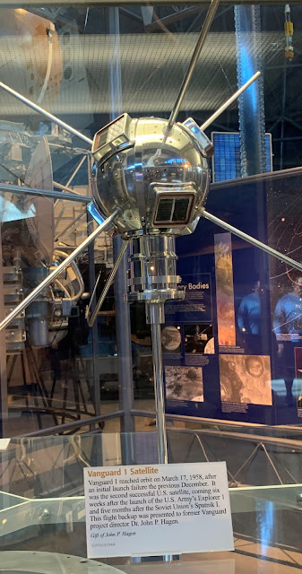
It just so happens that earlier in the week I was out at the Air and Space Museum facility near Dulles Airport, where I saw this flight backup of the Vanguard satellite: 

Tuesday, February 9, 2021

Meet Your New Soviet Neighbor -- With Hallicrafters

 
Thanks to Jeff Murray for alerting us to this.  It is obviously from World War II.   If the new neighbors had S-38s, well, that might help explain why things didn't go so well.  

Saturday, September 5, 2020

Taming Glitches in a Soyuz Space Clock (Plus -- Inside a Logic Chip and How Crystals Work)


Thanks to Bob KD4EBM for sending this.  

There is so much good info in this video:  They crack open a logic chip and look at the internal construction (it is entirely understandable by mortal minds).  They use cool test gear to troubleshoot the clock from a Soyuz spacecraft.  They explain very clearly the series and parallel resonances of quartz crystals, then display these resonances on a very nice spectrum analyzer.

The creator of the video is CuriousMarc.  He has many other interesting projects: 

https://www.youtube.com/c/CuriousMarc/featured

https://www.curiousmarc.com/ 

His bio is here: 

One paragraph from his bio really resonated with me: 

Working on this old stuff forces me to deal with the very fundamentals of electronics (and electro-mechanics). The principles are exactly the same as today, but nothing is hidden in mysterious circuits - you can understand and fix everything. Years of Moore's law has sure given us gobs of transistors, oceans of memory and a glut of gigacycles, but many times, particularly in consumer hardware, these are simply used to cover up poor and inefficient designs - and resource devouring software. What Intel giveth, Microsoft taketh away, as they say. It often irritates me that my PC takes several seconds to react to a simple command, in which time it must have executed billions of unnecessary instructions and consumed a few gigabytes of memory, no one knowing exactly what for anymore. Nothing like this in old high-end hardware: designs are pure and efficient, and the lack of resources is compensated by engineering mastery and immense cleverness, which is a joy to reverse engineer. Not only does it teach us timeless electrical fundamentals and engineering tricks, but it also gives us a much better appreciation of today's tech. How did all the technology we take for granted came to be? It will make you a far better engineer and inventor if you take the time to be a thorough student of the inventions of your illustrious predecessors.

Sunday, August 13, 2017

Audio Clips from N2CQR/HI8 Contacts with MIR Space Station (now in mp3)


Back in 1995 I was in the Dominican Republic.  I used an old 2 meter rig and a homebrew 5 element quad (see below) to talk to U.S. Astronaut Norm Thagard on the MIR space station.  (You may have heard me bragging about this before.) I made a bunch of audio clips from the contacts.  They'd been in the now defunct RealAudio format, but I have been able to convert them to mp3.  You can listen here: 

http://www.gadgeteer.us/CLIPS.HTM


Sunday, April 16, 2017

Micro-Shocks (and QRP Power?) from Nearby High Voltage Lines (video)


I spotted this on Hack-A-Day.  It caught my attention because many time, while riding my bike along the Washington and Old Dominion bike path, I have felt electrical shocks from the handlebars. 
Now, before you all conclude that OM Bill is losing it and start suggesting that I wear an aluminum foil hat, realize that the bike path is directly under some seriously high voltage power lines.  And that esteemed UK newspaper "The Daily Mail"  confirms that these shocks are, as the kids say, a thing.
http://www.dailymail.co.uk/news/article-2655190/Cyclist-told-grab-metal-bike-time-rides-overhead-power-line-gives-ELECTRIC-SHOCK.html
So think these Russian dudes are onto something.  How long will it be before the QRP community starts exploiting this power source?   (Please be careful about where you put the antenna!)

Tuesday, March 21, 2017

FB IBEW HB DC CW de UAE: A65DC's International Homebrew Rig


Good evening!

After my JOO moment, Bill put me in contact with Pete Eaton, who suggested that I would have a look at the schematics for K4GC 40m CW Transceiver.
And I did, It was just perfect for me, low part count, lots of things done in software!!! Perfect Bryan!


I started off the build and both Bryan and Pete supported me along the way, thank you! 

So here we have it:

The design slowly deviated further and further from the original, but I think I learned quite a lot by starting to make it “my own”.

The Arduino was changed to an UNO, yeah they are clunky and big, but I was not shooting for a pocket-size anyway… and they do have a proper USB port.
The RF-path is now switched by a relay straight after the filter, when the relay is relaxed the antenna is connected to the mixer, when I touch a paddle it connects to the TX circuit.
I have a short hang time from the last key input and it goes back to RX, VOX Delay I guess.

I completed the 700Hz bandpass filter, boy! this makes it a much nicer rig to work CW, I originally I skipped this filter for no good reason? That is the board standing up in the picture.


The TX circuit is a two stage, the first stage is a replica of VK3YE beach40 amplifier circuit, that also uses DB139. The second stage is a spin of the EMRFD Page 2.38 IRF511 Amp.
I have cranked it up to 17w, but it gets too hot too fast, as you can see I don’t have any proper cooling yet, I need to redo this board and plan for the heatsink a bit better.. it is now set around 10w, still getting hot, "599 TU 73”.
To be honest my CW does not go much further anyway, but I guess with this radio now completed I have one more reason to get my speed up.
 I use for convenience both CLK0 and CLK1, when I go into TX I switch off CLK0 and do the keying on CLK1, both transmitter stages are powered up the whole time (until I stop keying as described above)

As the 700Hz filter worked so superb, I decided that I wanted to introduce “modes” to the rig, I can now switch the audio either thru the filters (CW) or straight to the AF amp (AM).
I do enjoy listening around, and we have a lot of AM stations on offer in my region.

I kept the smart RX mute transistor circuit and when I ask the Arduino to change mode, it will mute the receiver quickly, pull the relay and then un-mute again, no ear pain from the loud relay click. (I am happy with that detail).

The 2 line display became a four line, and I can change Tuning Rate, RIT, Key Speed and Mode by using only the encoder and the one button built into the encoder.
The front panel sports, on off, Headphones, Paddle and volume, the display and the big knob.
Power connector and USB Port on the side. I did complete the CAT control changes while working on this radio, it now uses the classic Kenwood interface e.g. TS480. (A lot fewer questions from the PC to answer.)

The CAT control works very nice while using N1MM, it works a lot less nice using CQRLog, I guess it has to do with the number of times the software in the PC is asking about things from the radio.
I will look into logic to only worry about incoming serial requests if I have not answered for some time, and never answer while in TX…

By pressing the VFO button a small arrow appears next to TR, if I push again it moves the arrow down to RIT and so on.
if I turn the knob with the arrow standing in front of e.g. KEY it will increase or decrease the KEY speed, when I press again, it will return to frequency control.

Oh, another detail (that I am happy with) while the arrow is in front of the KEY, you can fiddle with the paddle with out transmitting.. practical for testing the speed.

So this is a K4GC transceiver with bits and pieces from VK3YE and bits from the A65DC laboratory in Dubai, truly international.

To trim things in I scheduled a QSO with a local ham here, and things worked very nice, later the same night I made my first “DX” contact with RM2D!!! Moscow!!
What are the odds that a Swedish guy living in the UAE makes the first contact to another Swedish ham who lives in Russia!

73,
Martin A65DC

Wednesday, August 31, 2016

A Signal for SETI? HD 164595


That's the Russian radio-telescope that picked up what was thought to be a possible signal from an extraterrestrial civilization.   This article from the SETI Institute has some interesting tech info on antennas and power levels.  Definitely not QRP!


Saturday, February 27, 2016

Sputnik Replica Transmitter, an "Error" in the Sputnik Schematic, and Why 20.005 MHz?


Mark K6HX pointed me to very interesting Hackaday article on Frank PA3CNO's Sputnik transmitter replica.  As blog readers will recall, we went through a period of Sputnik-mania a few years ago:  http://soldersmoke.blogspot.com/search?q=sputnik  Chief Designer Comrade Mikhail Rainey AA1TJ sent me some of the Russian tubes (like those pictured above). 

The Hackaday article pointed to our post reporting that Oleg RV3GM had found the schematic:
http://soldersmoke.blogspot.com/2013/04/sputnik-schematic-found.html   Stefan reports that PA3CNO found "an error" in the original Soviet schematic:
http://www.radio.cc/post/Franks-power-supply-for-sputnik    A mistake you say?   HAH, I say!  Hah!  This must have been part of a sinister commie plot to prevent the capitalist imperialists from ever being able to reproduce the glorious transmitter of the Soviet people.  They almost succeeded. 

Just kidding.  

In the course of looking through our old Sputnik posts, I came across a question I posted:

I have a question: OK so the crafty Soviets picked 20.005 MHz for some good reasons: Being so close to the WWV freq, it would be easy for hams and SWLs to find it with precision. In the November/December 2007 issue of "Break In" (from NZ -- thanks Jonathan-san!) ZL3DW notes that this frequency selection would allow a receiver set to exactly 20 MHz to "produce an audio tone plus or minus the Doppler shift without ever going through zero beat." But zero beat with what? Most of the receivers out there would not have had BFOs, right? So the Soviets wouldn't have been using ordinary CW, right? Were they using AM, with the beeps produced by an audio oscillator modulating the carrier? 

Was their diabolical plan to use WWV as the BFO for those using ordinary AM SW receivers?   If so, a 5 kHz separation from WWV seems to be too much right?  Especially when the Doppler shift on approach would push the frequency up a bit. Maybe they just chose this freq to make it easy for listeners to find -- just a bit above WWV.  Comrade Rainey surmised that they were keying the PA stage -- the oscillator "backwave" was at times audible on the ground.

What do you think Comrades?
DSW and 73.

Sunday, October 11, 2015

The Amazing History of the Gibson Girl Rescue Radio

 
A video about the Kon-Tiki expedition got us wondering about how you could generate hydrogen gas for an antenna balloon while on a raft at sea. (That's the kind of question that keeps Knack victims up at night.)  This led us to the Gibson Girl rescue radio.  This morning I found a fascinating web site that gives the long, multi-country history of the curvaceous rescue rig: 
 

Thursday, April 16, 2015

One more on Gagarin


Bill, Pete,

In keeping with historical events, I have enclosed a few snap-shots from the 1961 Pittsburgh Press dated Wednesday, April 12, 1961.
Yes, a few of us recall that very day. I had filed this newspaper in my Scrap Book back then. It was a bitter sweet thing, to read for most, as we hoped the U.S. to be first but none-the-less, we smiled anyway because, it proved a person could go into space and return. (Flight Breaks Barrier to Space Travel). I was very enthusiastic about Rockets, Travel and current events. I built my own capsule in the rafters of my parents home and spent all day up there in the tiny confines as I launched my own secret adventures into Outer-Space.

Hope you enjoy the photos. I can provide a better set of copies if you are interested.

73's

Harv - WA3EIB
Idaho Falls, ID


Harv:   I converted a small closet into what I saw as an excellent simulator of the Apollo 11 Command Module.  Bill


Our book: "SolderSmoke -- Global Adventures in Wireless Electronics" http://soldersmoke.com/book.htm Our coffee mugs, T-Shirts, bumper stickers: http://www.cafepress.com/SolderSmoke Our Book Store: http://astore.amazon.com/contracross-20

Cosmonautics Day Follow-up

Mark, K6HX, took a break from Hummingbird photography and captured some of the images streaming down from the International Space Station on Cosmonautics Day (April 11):  http://brainwagon.org/2015/04/11/sstv-from-the-iss/  
Very cool Mark (and I think the bird pictures are just as cool!)

Our book: "SolderSmoke -- Global Adventures in Wireless Electronics" http://soldersmoke.com/book.htm Our coffee mugs, T-Shirts, bumper stickers: http://www.cafepress.com/SolderSmoke Our Book Store: http://astore.amazon.com/contracross-20

Friday, April 10, 2015

Happy Cosmonautics Day! Yuri Gagarin Images (SSTV) from Space This Weekend

http://m0dcm.co.uk/?tag=sstv

From the ARISS Web Site:

http://www.ariss.org/news.html

Latest NewsApril 6, 2015

ISS Slow Scan TV Expected Weekend of April 11

In celebration of Cosmonautics Day, Russian ARISS SSTV activity is planned for the second week of April.

Cosmonautics Day celebrates Yuri Gagarin’s famous flight on April 12, 1961 becoming the first human to reach space.

The SSTV event is planned for Saturday, April 11, beginning at 10:00 UTC and continuing until 21:00 UTC. All transmissions will use the high resolution SSTV mode PD180. Transmissions will be at 145.800 MHz. If similar to past events, 12 different photos will be sent through the weekend with 3 minute off periods between transmissions.

To receive the images in real time, all that’s required is a 2 meter radio receiver and a computer to convert the receiver’s audio to image form. The software to do this is available as freeware on the internet at sites such as http://hamsoft.ca/pages/mmsstv.php.  Received images can be uploaded and viewed at the ARISS Image gallery found at http://www.spaceflightsoftware.com/ARISS_SSTV/index.php .

Those capturing images are encouraged to upload them to http://www.spaceflightsoftware.com/ARISS_SSTV/submit.php

Uploaded images may be viewed at http://www.spaceflightsoftware.com/ARISS_SSTV/

Please be advised that situational demands on crew time could result in postponement or cancellation of any ARISS activity. Please pay attention to the possibility of any change in scheduling.


Soviet Union-1965-Stamp-0.12. Cosmonautics Day.jpg


Our book: "SolderSmoke -- Global Adventures in Wireless Electronics" http://soldersmoke.com/book.htm Our coffee mugs, T-Shirts, bumper stickers: http://www.cafepress.com/SolderSmoke Our Book Store: http://astore.amazon.com/contracross-20
Designer: Douglas Bowman | Dimodifikasi oleh Abdul Munir Original Posting Rounders 3 Column